|
Introduction | Parts and assembly | Software stack | Download manuscript (V1) | V1 Page This page provides instructions on setting up the software stack (API) for programming over microMVP with a set of ten vehicles. The API will enable the vehicles to follow specific paths but do not guarantee that the vehicles will not collide. However, we do provide a demo showing how ten vehicles may be synchronized. These way point based APIs are sufficient for the vehicles to follow complex paths without collision. APIs enable more complex tasks will be gradually added as they are fully tested and ready. Toward the end of the page, instructions are provided on how to add additional vehicles to the system. The source files needed for this part can be downloaded here. Note that this page is meant for an audience comfortable with python and is not intended for general educators. We plan to make more readily usable open source distributions available for primary and secondary education in the near future with plain, easy to follow instructions. Packages to be installed The following libraries should be installed before proceeding. We assume that the end user has basic knowledge when it comes to setting up these libraries for the purpose of program compilation. OpenCV 2.x and up ZeroMQ 4.x chilitags Arduino IDE pygame pyserial pgu munkres We assume the user has boost library installed as well. Enabling vehicle tracking
> detect-live.exe cameraID port For example, running "detect-live.exe 0 5556" will use camera 0 (the first camera of the system) and starts feeding tag positions within the camera's range on port 5556. Note that for best tracking, one should adjust the camera parameters (using openCV or camera driver software if available) including exposure, brightness, contrast, white balance, and so on to make sure the tags within the camera range are consistently tracked (the number of tags seen by chilitags is displayed at the top left corner of the tracking app. See picture below for a screen shot of the module while running. Note that all six tags are tracked. We set the camera to run at 1280x720 resolution, which appears sufficient for the purpose of tracking. This can be set to 1920x1080 if desirable.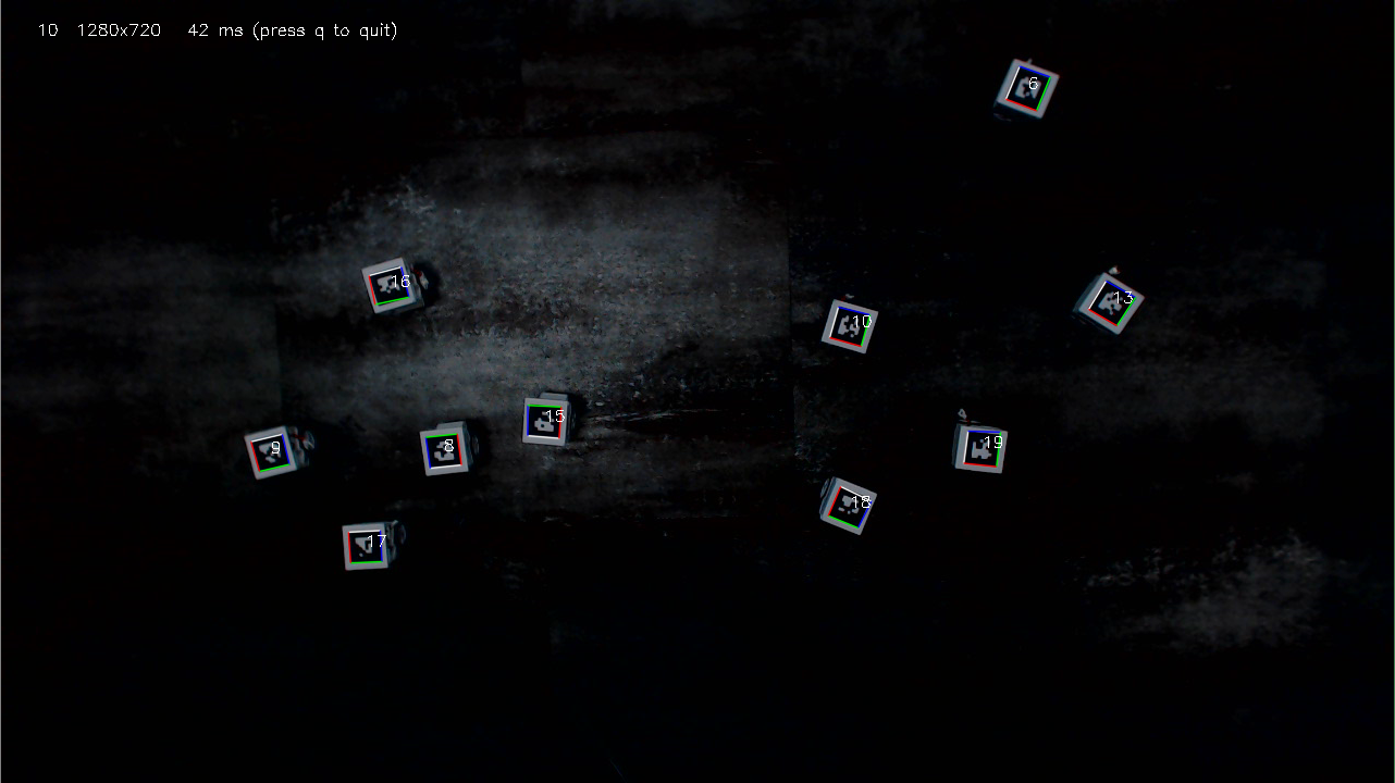 Once the vehicle position data publisher is started, one may test the data feed using positionZMQSub.py under the root folder as (make sure that the parameters in globals.py are set according to your setup) > python positionZMQSub.py tagID in which tagID is the chilitag ID (displayed on the tracking program UI window) for a given vehicle. For example, suppose that a vehicle with tagID 29 is in the camera's range, then running python positionZMQSub.py 29 should produce an output like the following
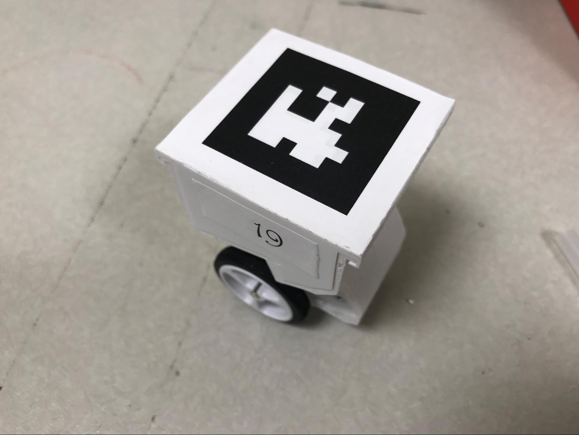
Collecting update from server: tcp://192.168.1.10:5556 Flashing the CrazyRadio firmware The communication between the vehicles and the main control computer is done through CrazyRadio. After plugging in Crazyradio dongle in your computer, for Windows users, the crazyradio driver should be installed before doing next steps (the full instruction can be found here: wiki), while for Mac OSX and Linux users, no driver is needed to install. When using the dongle for first time, the Crazyradio PA firmware should be built and flashed. (This step can be skipped after the first setup). The full instruction can be founded here: wiki. Note that this step should be done in Linux/Mac OSX environment. Radio Configuration Crazyradio is configured in PTX mode. It can communicate with Nordic chips compatible with the nrf24L family (at least nrf24L01p, nRF51 and nRF52 tested). In order to communicate with the Crazyradio the target has to be configure correctly: -PRX mode -One active pipe with the address configured in the Crazyradio dongle, by default it is 0xE7E7E7E7E7 -5 byte address -Dynamic payload length enable -Payload with ack enable Programming and testing the CrazyRadio The radio based vehicle is fully compatible with Arduino and can be easily set up so that the vehicle can be programmed with the Arduino IDE. In the IDE, compile and upload the Arduino code (radio_ININ2.ino) via the USB port on the Arduino board. Note that for each vehicle, a different carID should be used. For ten vehicles, these IDs can be 1-10 or any number you want without duplication. One should know which vehicle has which carID (putting a tag on its side). Leave all other fields to have the default values. Once this is done, when two such radio cars are powered up, they can readily communicate with each other. To test that a vehicle is indeed working fine, run CrazyRadioMVP.py under the root folder as > python CrazyRadioMVP.py carID right_thrust left_thrust in which carID is the ID of the vehicle (the same carID used in the .ino file when flashing the vehicle's Crazyradio). and right_thrust and left_thrust are the speed rate of two wheels. This should run the given car for 3 seconds before turning them off.Control single/multiple vehicles using GUI To visualize the running of all vehicles and do various patterns, we design a pygame based UI Windows to simulate all vehicles' movement. After turning on the vehicles, put them under camera and run the position_.exe as mentioned above, we run gui.py under root folder as > python gui.py The camera would first sense the tags on the vehicles and store them in the utils.carInfo, and then run the UI window. That means, you would not need to type in carInfo manually.Note if you want to run simulation solely without running actual cars, you can simply add "-s" after this command line. You would see the following window: 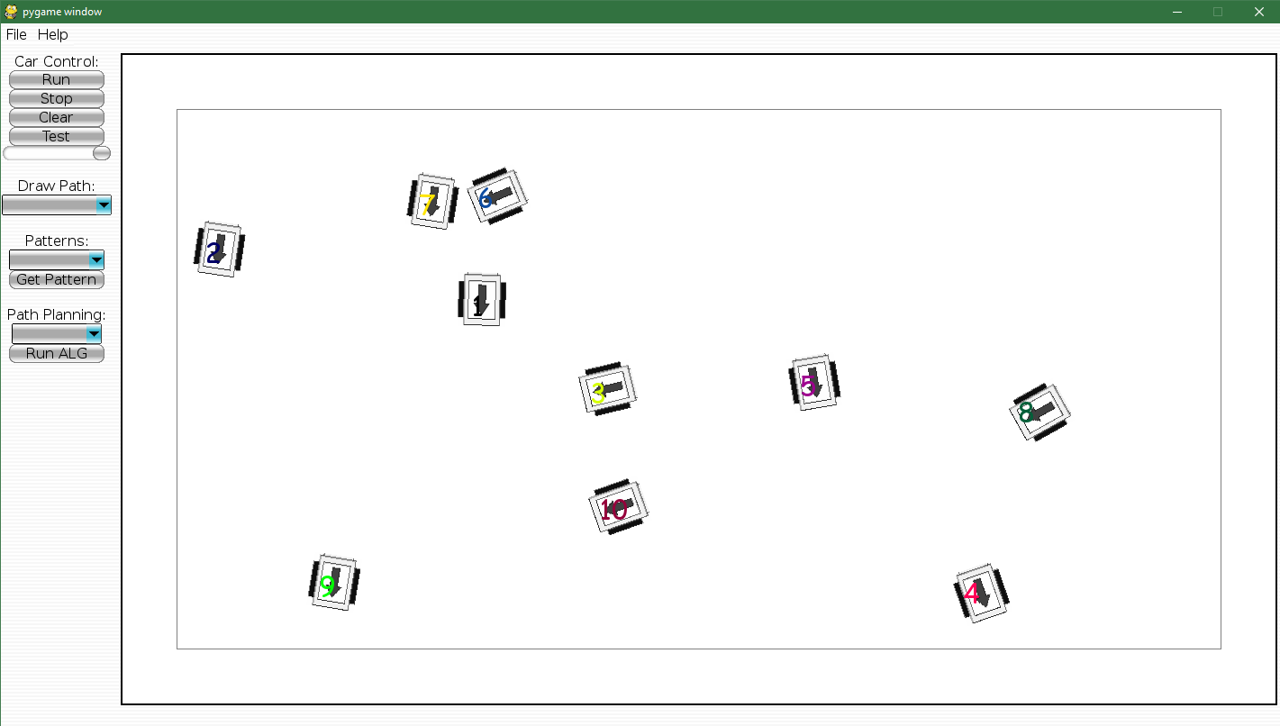 The arrow on the car shows the direction of the car, and the number shows its tag number. In the left bar, we have "Car Control", "Draw Path", "Patterns" and "Path Planning" four parts. Outside simulation mode, you can run "Test" button to test whether all cars working before doing next steps. After checking vehicles' status, choose a movement mode for the vehicles. An user can use the mouse to draw any arbitrary paths inside UI or choose a pre-designed pattern or path planning algorithm. All paths would be visualized in different colors after drawing or choosing the mode. Then click "Run" to start sending speed to each vehicle to let them move. Note that the horizontal bar below "Test" can adjust the speed of all vehicles. If you want to stop the system, simply click "Stop". The "Clear" button is used for clean all previous patterns shown on the screen. Control single vehicle: More complex patterns can be readily added by dissecting the pattern into a list of way points. The pre-set examples are in "patterns" and "algorithms" directories. Some pre-set patterns/algorithms: 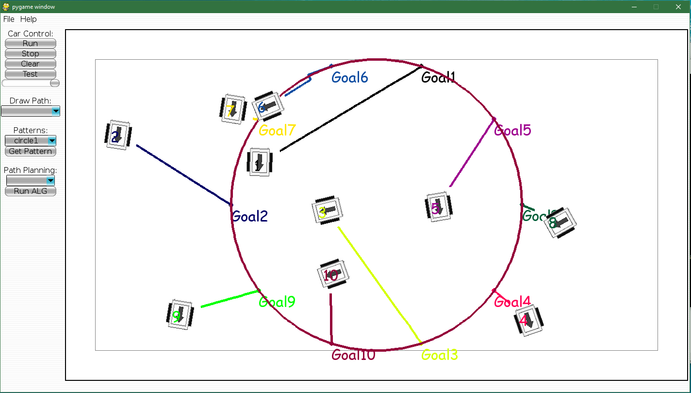   More design elements The GUI file is constituted by multi-threading, in which each thread keeps running and refreshing in a very high frequency. Among four threads, one thread draws the show window, one thread reads cars' position information from camera, one thread calculates the speed and path for each vehicle, and one thread sends speed. In such way, we ensure all parts work simultaneously. All info for vehicles are stored in "utils.py", which can change the size of cars -- wheelbase, the tag size of cars and other UI design. Adding even more vehicles For CrazyRadio chip, the default maximum size of one block would be 32 bytes. The block is identified by the first and last byte. The middle 30 bytes are wheel thrusts for 15 vehicles. Currently, in order to control more than 15 cars, we send a list of commands once, in which the size of the list depends on the number of vehicles. Although delay exists, it's too tiny to be considered. This method is the most straightforward one. Alternatively, you can change the length of block by programming on nRF24L01 chip, which is also doable. However, with more vehicles added, the radio chip would have higher probability to interfere with each other. Hence, running fewer than 30 vehicles simultaneously would be a proper choice. Return to top | ||