|
Introduction | Parts and assembly | Software stack | Download manuscript (V1) | V1 Page Components In designing microMVP, emphasis was put on making the system readily reproducible by robotics researcher, educator, and hobbyists alike. We did extensive study to ensure that the parts we select are reasonably easy to obtain, easy to use, and reasonably affordable. This is of course an evolving process and will continue improving the availability and affordability of the components of microMVP with each iteration. Below is a list of all parts used in the microMVP vehicle version 3, including some suggested wires and connecters for connecting the components. Note that reference prices are pulled in July 2018 and may have since changed. The price assumes volume purchase for building 10+ vehicles. The second table lists the few parts for the tracking platform. Vehicle parts
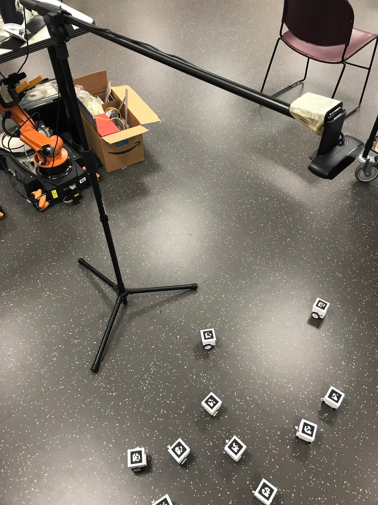
Tracking and control platform
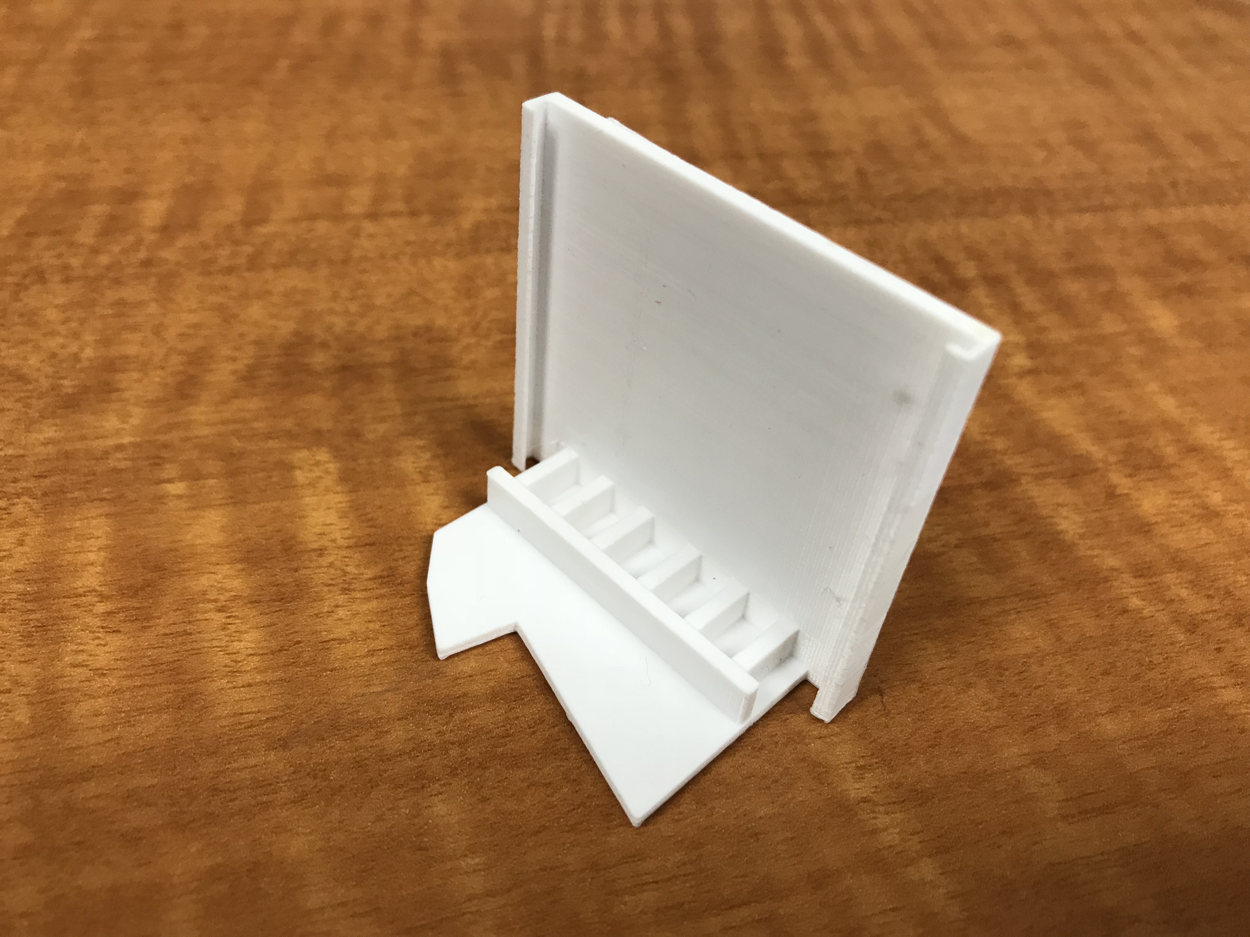
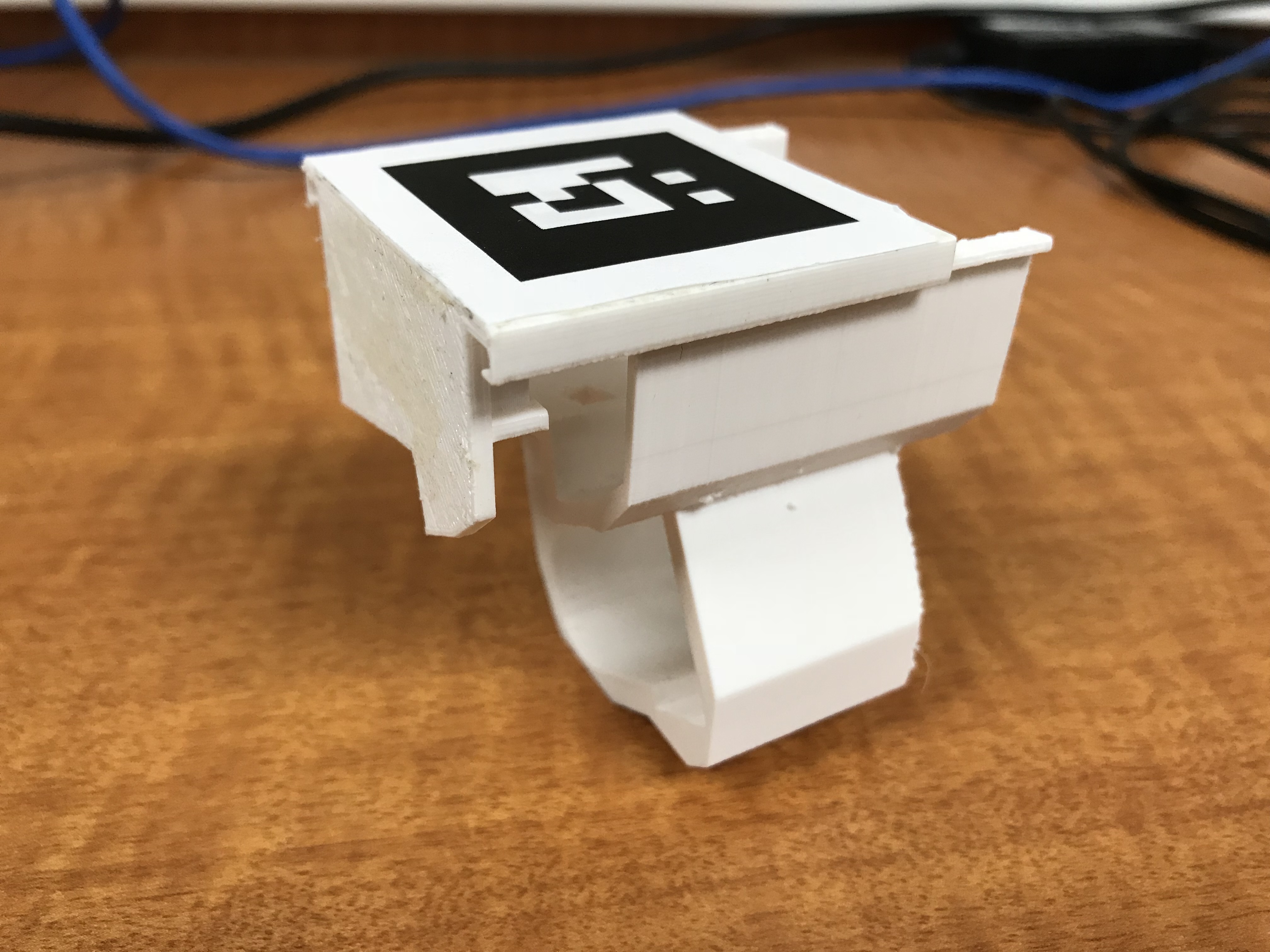
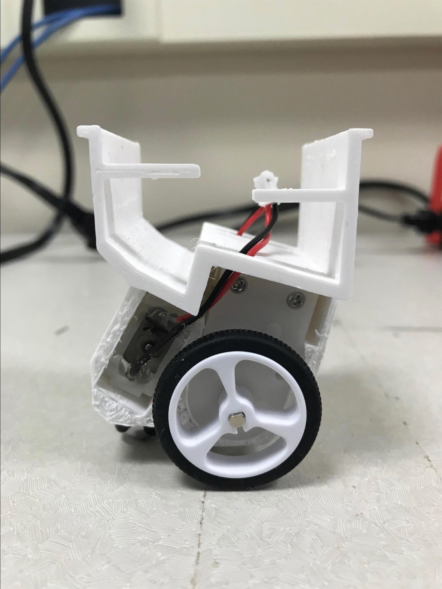
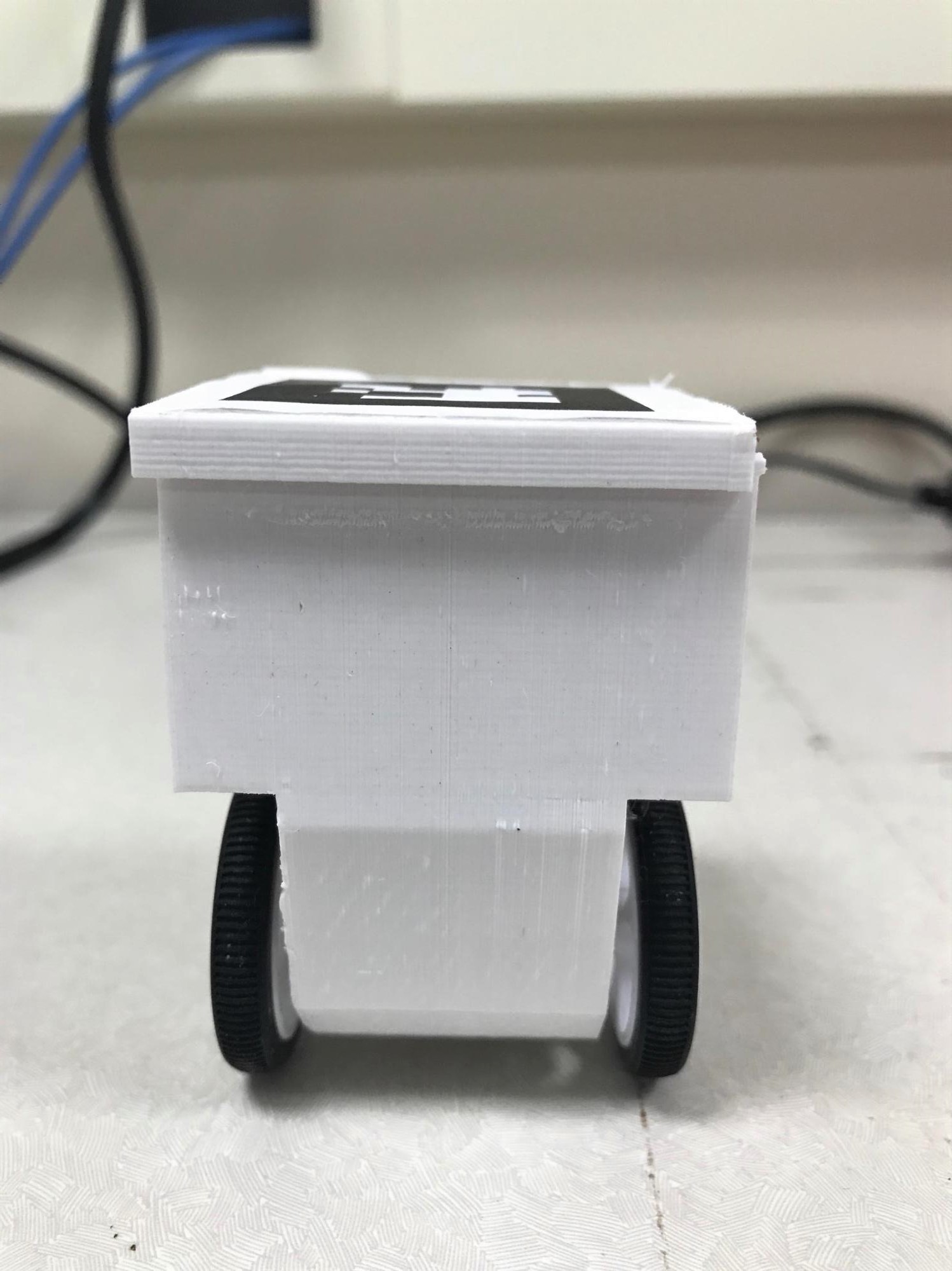
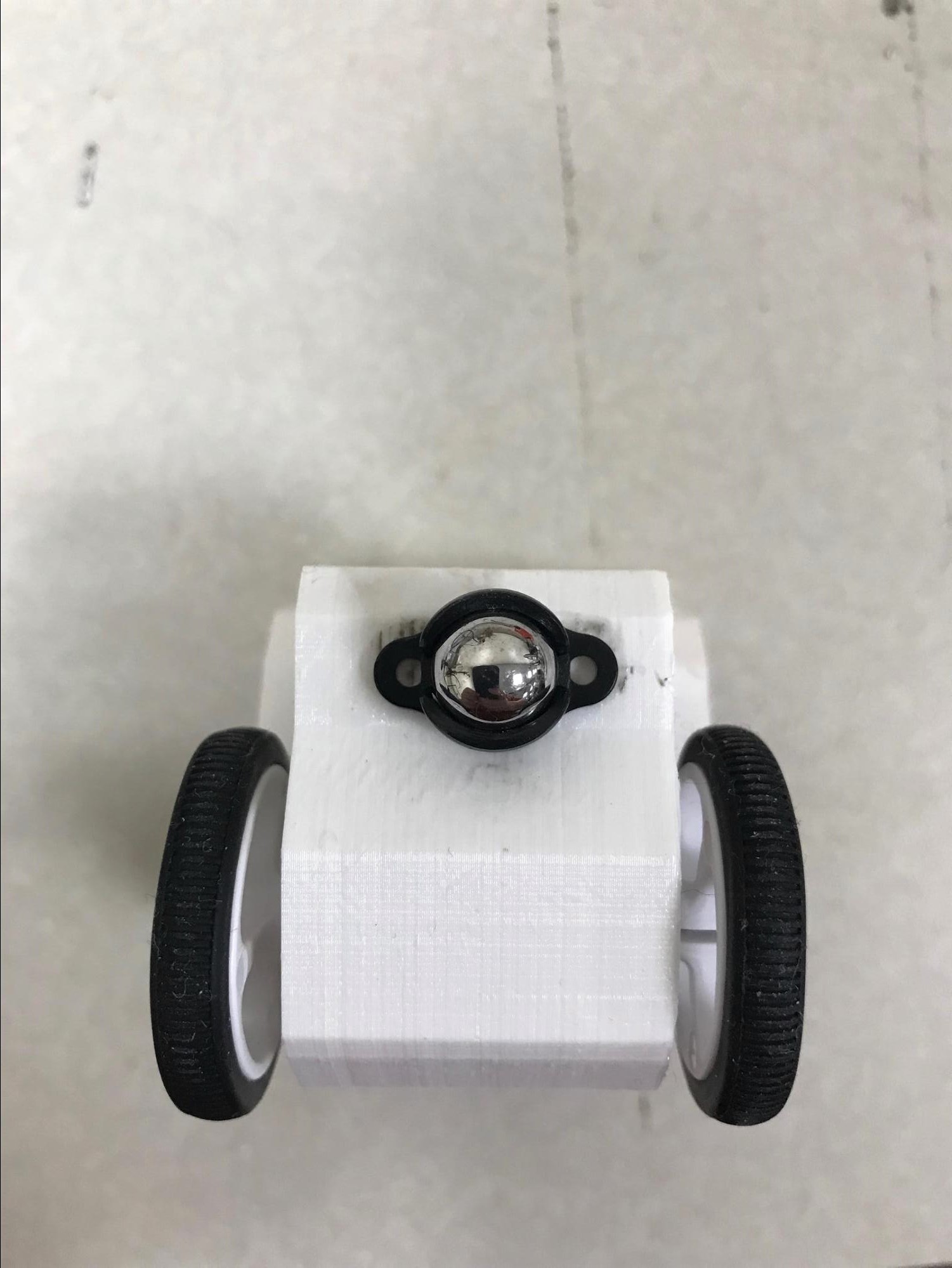
Putting together the vehicle Printing and readying the shell The shell (.stl) of the vehicle are two pieces, including body and cap, that can be printed on any working 3D printer. We tested printing on a 50K USD stratasys printer as well as a 180 USD monoprice mini 3D printer. Once the two pieces of shells are printed, the cap can be easily installed and removed at the top of car body. Below are pictures of the separately printed shell pieces, including body and cap, and the half assembled shell, which shows the direction to put cap on the body. The caster ball should be glued on to the bottom of the assembly as well after wheels installed (using only the ball assembly and the thicker 1/8" spacer). 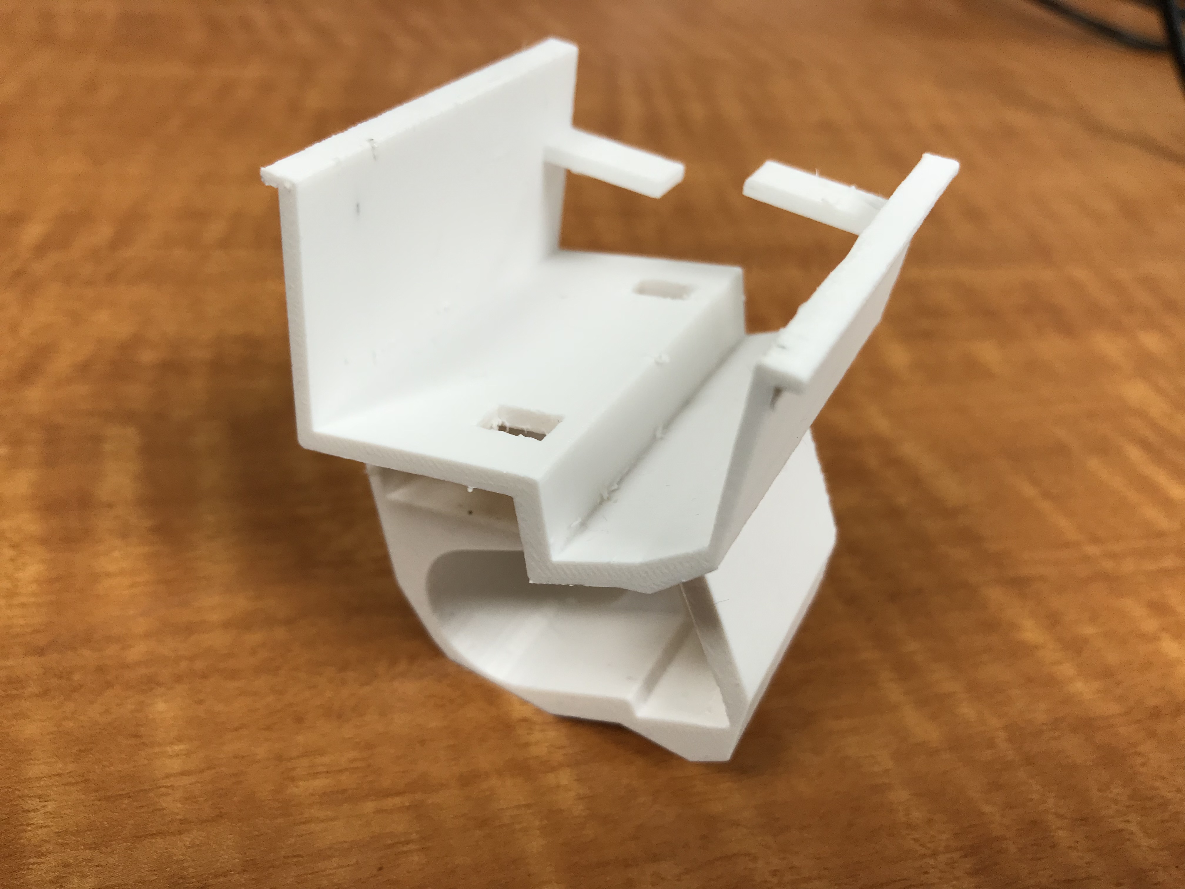
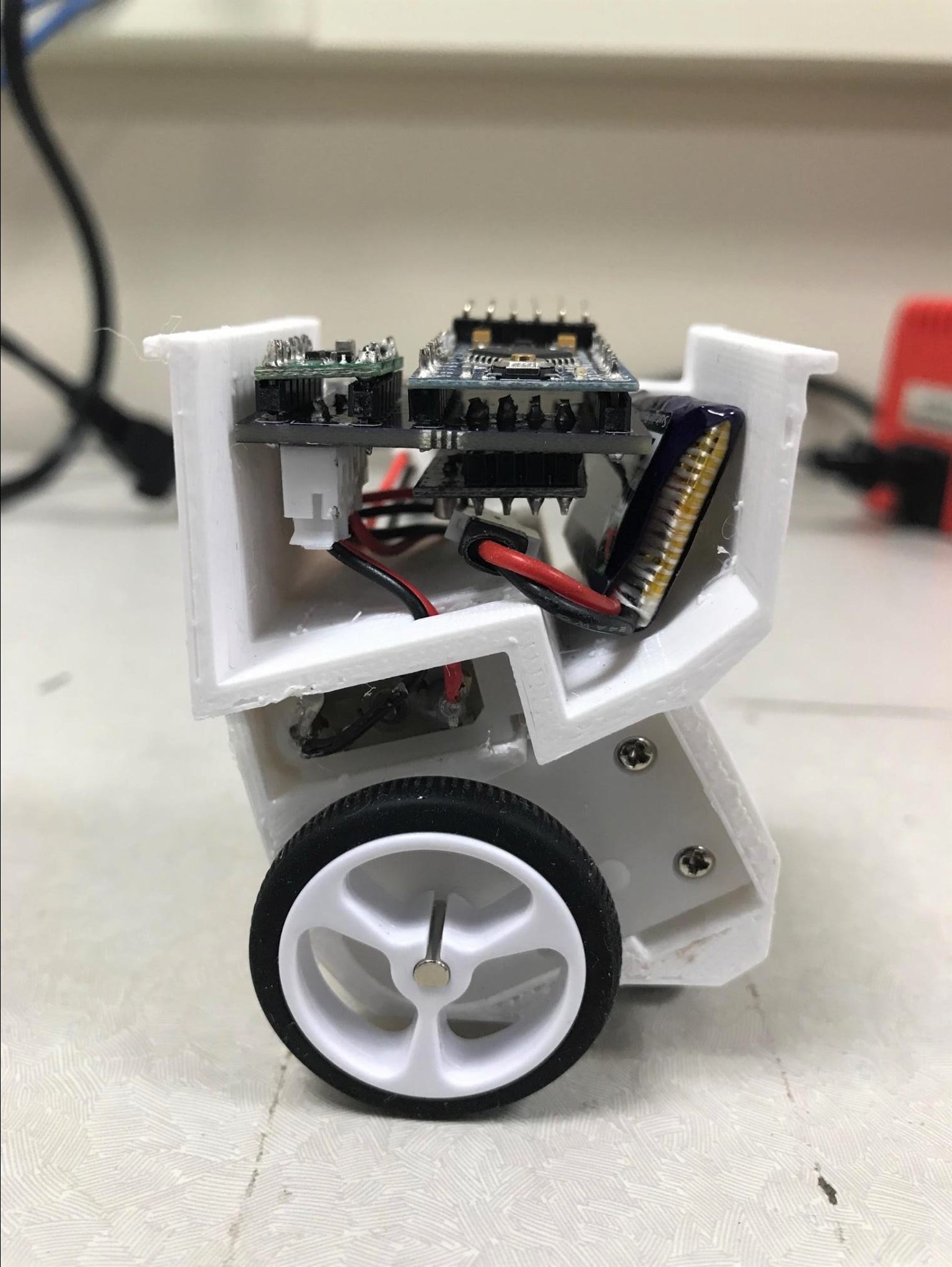
Soldering together the components The micro-vehicle requires the soldering of a few wires and parts on the PCB board, including the pololu DRV8835 dual motor driver carrier, the motors, the Arduino board, the wireless nrf24l01 module and switch. In order to make the vehicle more robust, we use break away headers instead of wires to connect each part. The schematics we use for connecting the wires are given in the picture below. Because the Arduino board offers more output pins than we need, the schematics for doing the soldering is not unique. Below is the schematic used for soldering. 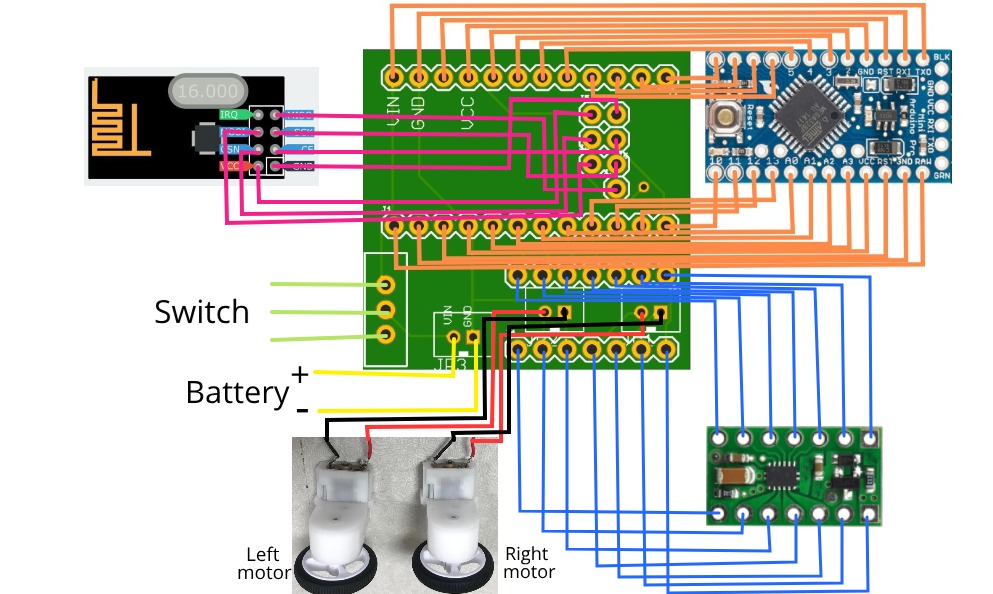 After soldering, we would have a connected part of chips as following: 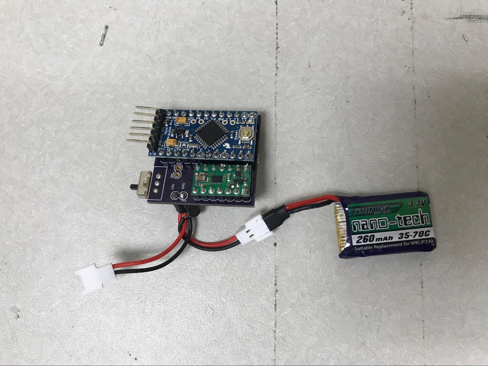
 Installation process: As you can see below, the motors and the PCB board can be soldered separately at first. Then put the motors in the lower space of the car body. When they are put in the correct places as shown in picture, you can simply plug in the connecting header to connect chips and motors. In this way, it would be easier for people to dissemble the PCB board without get rid of the motors on the car shell. 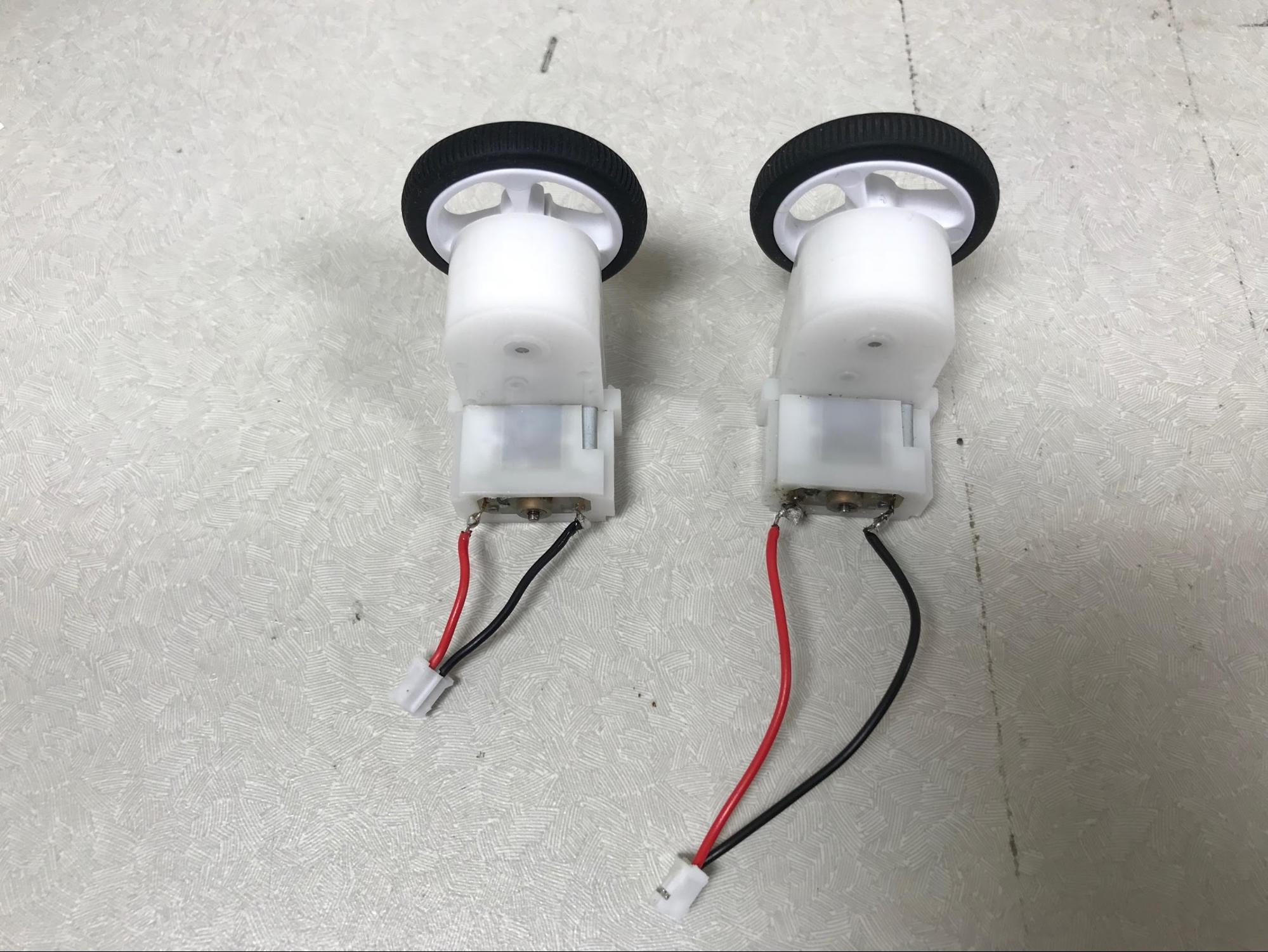
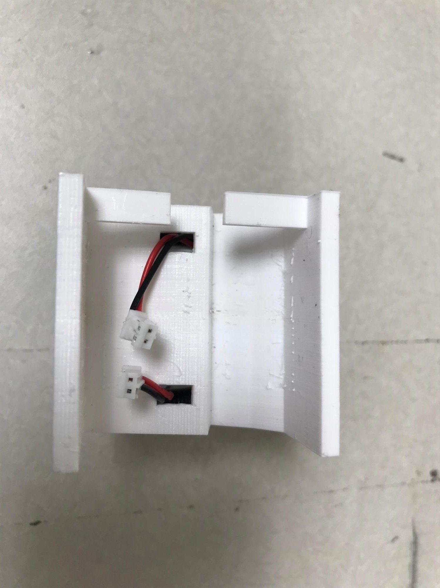
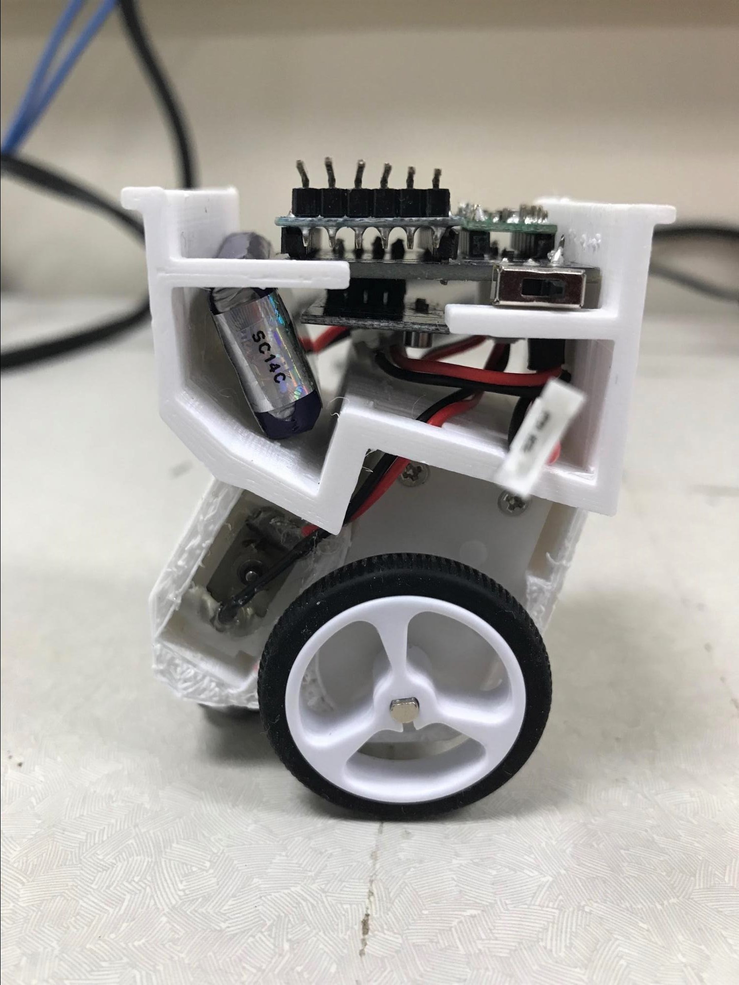
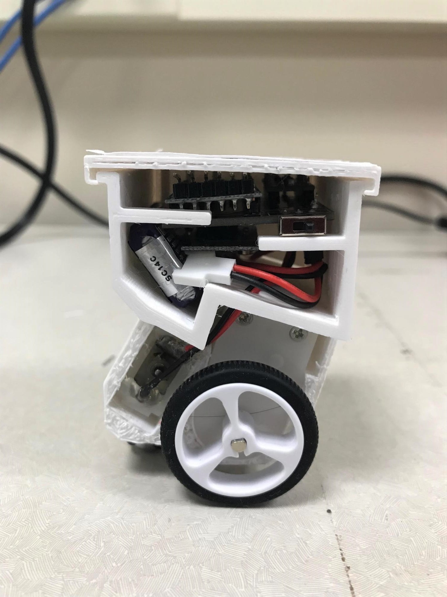
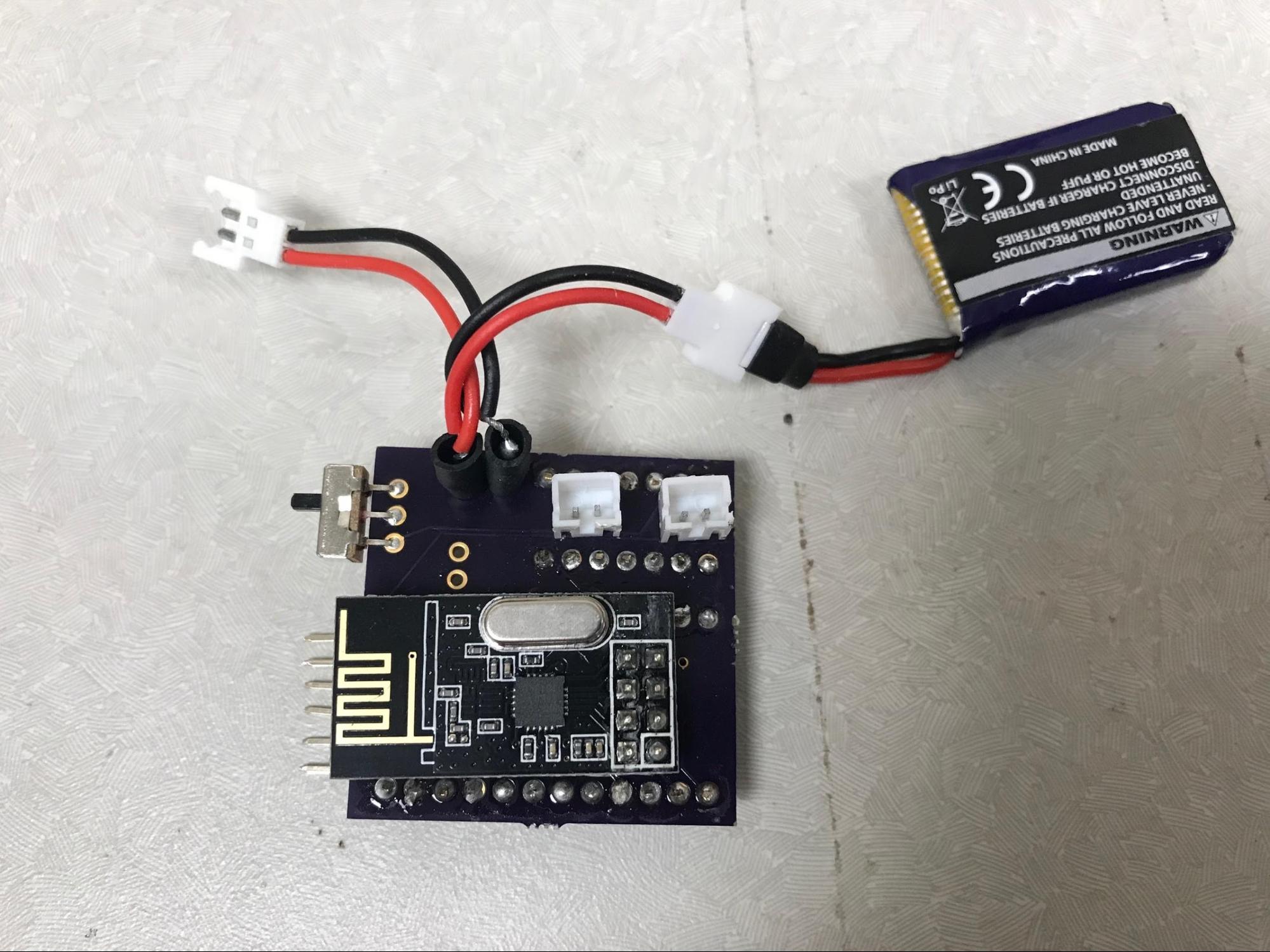
We also add one more set of wires together with battery wires for the charging purpose. It has been tested successfully for correct charging. But it is totally optional for you to include this design or not. *Caution: in the upper space of the vehicle where the PCB board is installed, which can be narrow, be careful to avoid direct touch between charging wires’ sockets and PCB board. It can result in short circuit and the parts on PCB board can be broken! Camera platform
| |||||||||||||||||||||||||||||||||||||||||||||||||||||||||||||||||